Box electronics design notes
Assegid Kidane, AME / Synthesis, ASU
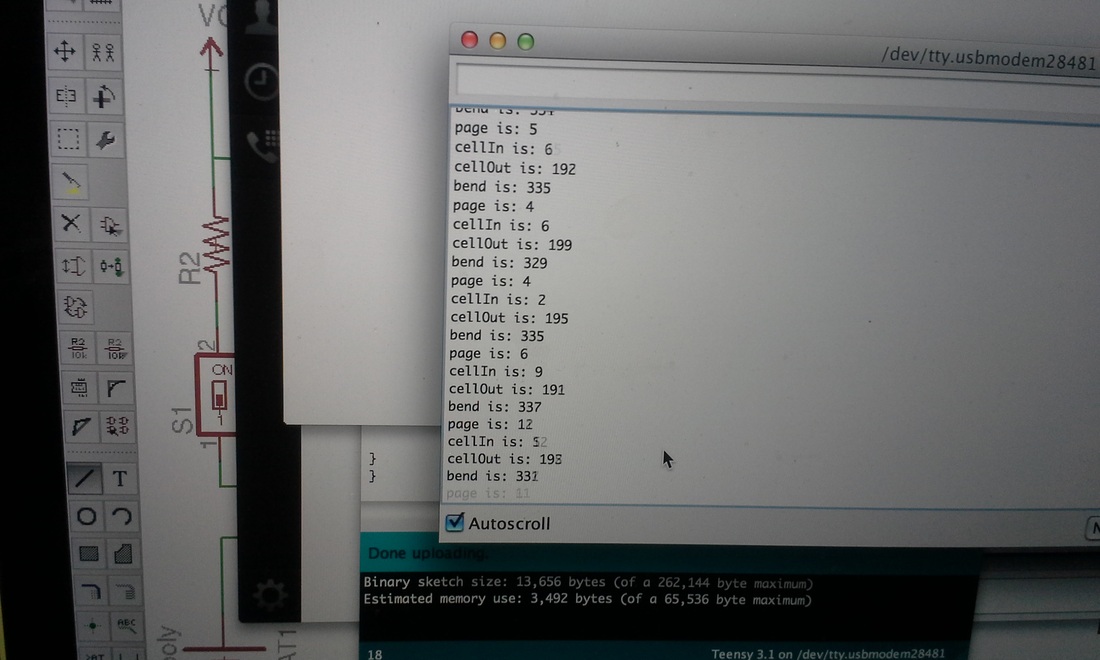
Test readings for programming:
cellin open 719 closed 30
cellout open 204 closed 20
page none 15 one 65 two 140
bend straight 340 bent 790
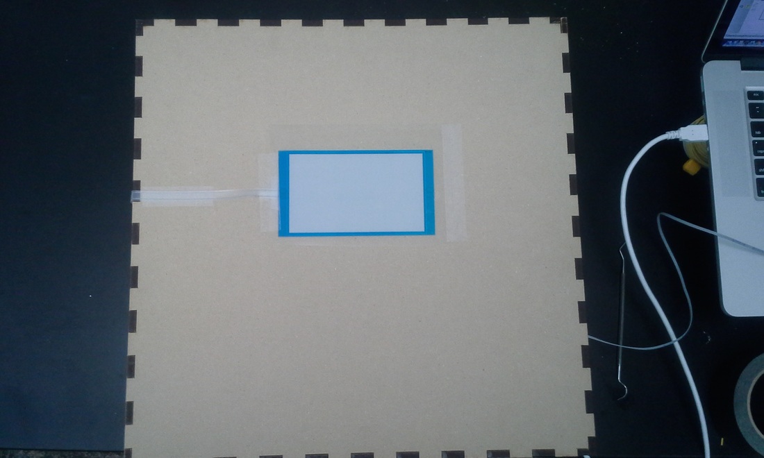
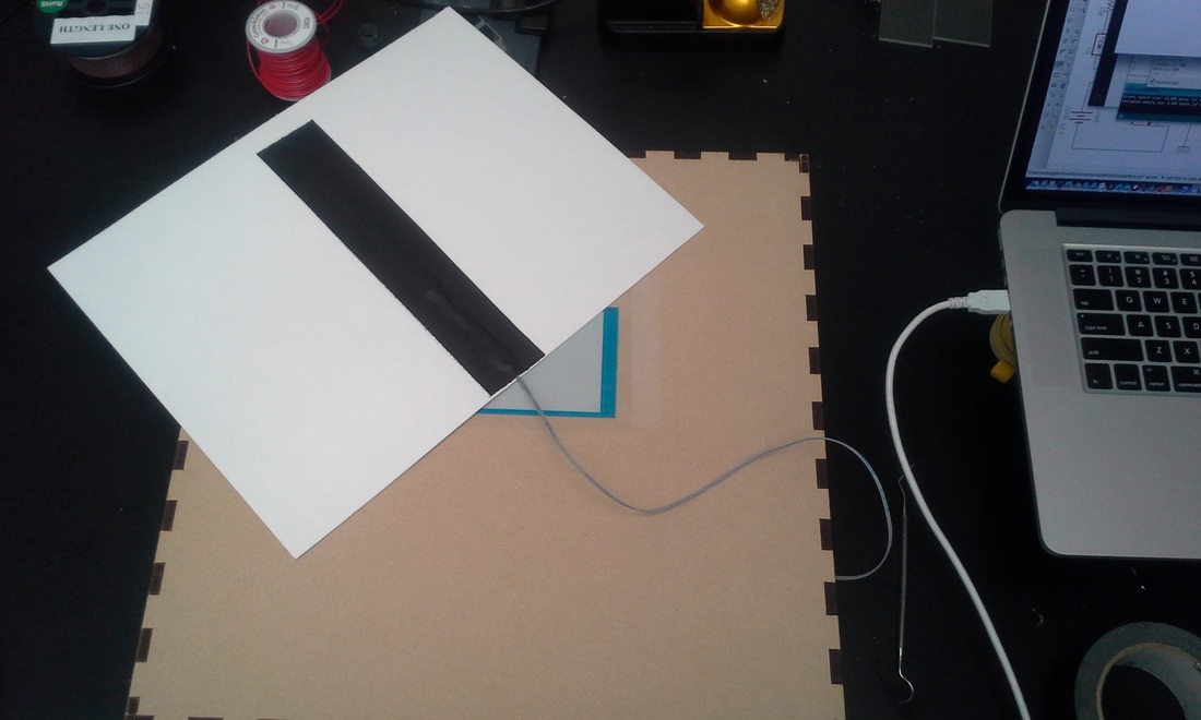
Page sensor:
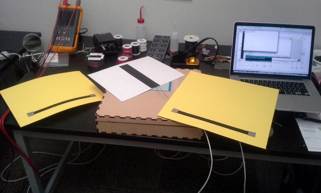
Page sensing uses an analog input to determine the voltage input based on the number of pages stacked. Each page adds 100kohm resistance in parallel with previous pages to VCC(3.3V) against a 10kohm to ground. The current pages use velostat material to produce the 100kohm resistance.
The center of the contact points are 11” apart.
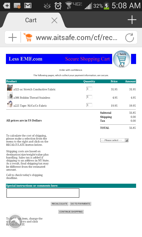
The velostat material has 7kohm/square.
To use 10.5” length of velostat between the contacts having a resistance of 100kohm, the width needs to be 0.73”.
Alternatively, we can use 100kohm surface mount chip resistor with conductive tread or copper foil etc.
Sound output:
This design is based on using the teensy audio shield which I do not have and Navid and Chris are working on. Consequently, all pins that will be needed for the audio shield are open and available. In fact, one can add the audio shield on the current circuit, reprogram the teensy with the audio code and library added, modify the logic as needed and the device should work without a problem.
I am currently using the digital pin 4 to produce the tones for the speaker. After adding the shield, you would be using the line out from the shield instead to the current speaker amplifier(yellow line) or to the line-in input of the amplifier and speaker you decide to use, if you choose to use something else.
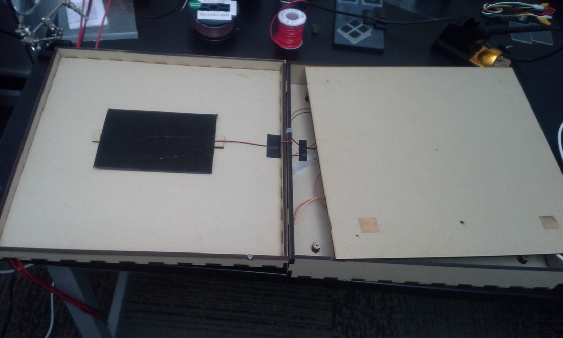
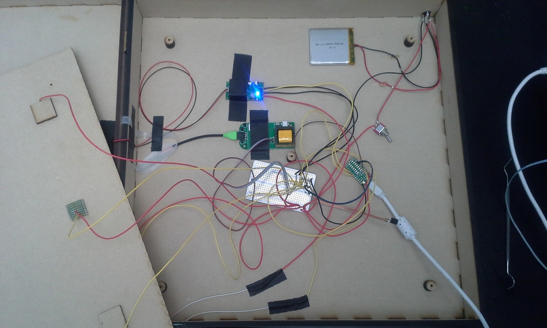
Elastolite display:
The Elastolite module controller has 3 input wires. V_bat(3.7V), ground and control.
The display has 4 modes of operation. 1 Hz blink, 4 Hz blink, steady ON and OFF. Sorry, these are estimates as I have not measured them and I have not found information from the manufacturer either. In order to cycle through the different modes, the control line need to be switched LOW for one second and back to HIGH. Currently, when the device is turned ON the teensy is programmed to cycle through all the modes and stop in the OFF condition.
When the box is in an adequately lit space a brief (less than 1 second) blockage of cellOut(photocell on left side of box sensing box exterior light) will activate the elastolite to the steady ON condition.
Blocking the photocell for 3 seconds will turn the elastolite OFF.
Battery Life:
Device was tested in worst case conditions; Elastolite ON and speaker beeping loud at 1hz due to ‘page-2-on’ condition. Battery life for this condition was 3.75 hours. I estimate under regular use conditions it should last 6 or more hours. If necessary, with a larger battery, it can work for several days without requiring a recharge.
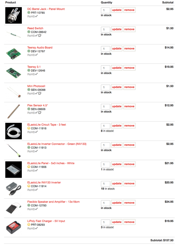
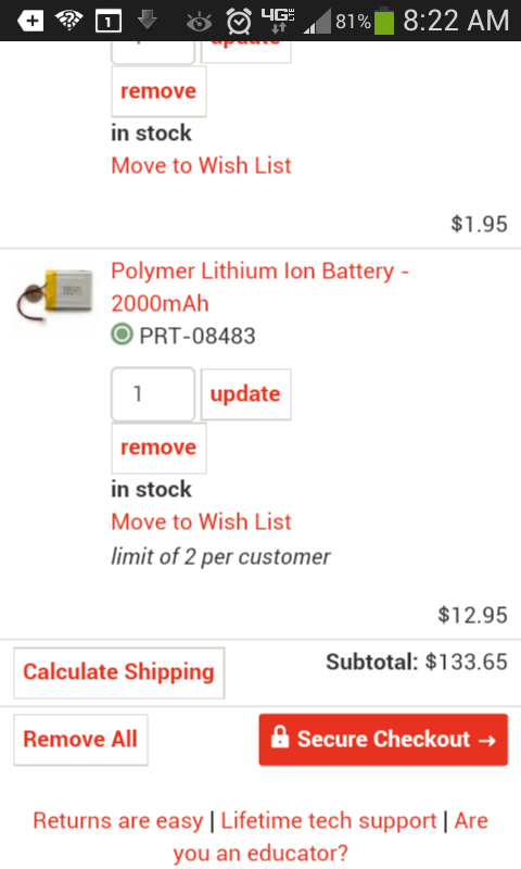
Parts used:
http://www.frys.com/product/7309494?site=sr:SEARCH:MAIN_RSLT_PG
http://www.homedepot.com/p/Unger-1-1-2-in-Safety-Scraper-Replacement-Blades-for-Glass-No-9-Standard-100-blades-UNG-SRB10/203014072?MERCH=REC-_-PIPHorizontal1-1-_-NA-_-203014072-_-N
each blade makes 2 metal inserts for each contact of a page.
https://www.sparkfun.com/products/12793
https://www.sparkfun.com/products/11906 and connector and inverter
Test readings for programming:
cellin open 719 closed 30
cellout open 204 closed 20
page none 15 one 65 two 140
bend straight 340 bent 790
Page sensor:
Page sensing uses an analog input to determine the voltage input based on the number of pages stacked. Each page adds 100kohm resistance in parallel with previous pages to VCC(3.3V) against a 10kohm to ground. The current pages use velostat material to produce the 100kohm resistance.
The center of the contact points are 11” apart.
The velostat material has 7kohm/square.
To use 10.5” length of velostat between the contacts having a resistance of 100kohm, the width needs to be 0.73”.
Alternatively, we can use 100kohm surface mount chip resistor with conductive tread or copper foil etc.
Sound output:
This design is based on using the teensy audio shield which I do not have and Navid and Chris are working on. Consequently, all pins that will be needed for the audio shield are open and available. In fact, one can add the audio shield on the current circuit, reprogram the teensy with the audio code and library added, modify the logic as needed and the device should work without a problem.
I am currently using the digital pin 4 to produce the tones for the speaker. After adding the shield, you would be using the line out from the shield instead to the current speaker amplifier(yellow line) or to the line-in input of the amplifier and speaker you decide to use, if you choose to use something else.
Elastolite display:
The Elastolite module controller has 3 input wires. V_bat(3.7V), ground and control.
The display has 4 modes of operation. 1 Hz blink, 4 Hz blink, steady ON and OFF. Sorry, these are estimates as I have not measured them and I have not found information from the manufacturer either. In order to cycle through the different modes, the control line need to be switched LOW for one second and back to HIGH. Currently, when the device is turned ON the teensy is programmed to cycle through all the modes and stop in the OFF condition.
When the box is in an adequately lit space a brief (less than 1 second) blockage of cellOut(photocell on left side of box sensing box exterior light) will activate the elastolite to the steady ON condition.
Blocking the photocell for 3 seconds will turn the elastolite OFF.
Battery Life:
Device was tested in worst case conditions; Elastolite ON and speaker beeping loud at 1hz due to ‘page-2-on’ condition. Battery life for this condition was 3.75 hours. I estimate under regular use conditions it should last 6 or more hours. If necessary, with a larger battery, it can work for several days without requiring a recharge.
Parts used:
http://www.frys.com/product/7309494?site=sr:SEARCH:MAIN_RSLT_PG
http://www.homedepot.com/p/Unger-1-1-2-in-Safety-Scraper-Replacement-Blades-for-Glass-No-9-Standard-100-blades-UNG-SRB10/203014072?MERCH=REC-_-PIPHorizontal1-1-_-NA-_-203014072-_-N
each blade makes 2 metal inserts for each contact of a page.
https://www.sparkfun.com/products/12793
https://www.sparkfun.com/products/11906 and connector and inverter
/* QI4Q box control code Assegid Kidane July 2014 */ int i; int door; int cellIn; int cellOut; int page; int bend; int speaker = 4; int Tone; int el = 5; int darkLim = 80; boolean elState = LOW; void setup() { Serial.begin(38400); pinMode(el, OUTPUT); pinMode(speaker, OUTPUT); pinMode(8, INPUT); delay(5000); for (i = 0; i < 4; i++){ Serial.println("debug"); digitalWrite(el, LOW); delay(1000); digitalWrite(el, HIGH); delay(1000); //to self calibrate external photocell to trigger for small changes in a specific space, //uncomment code below and turn box ON at location where it is going to be used. darkLim = analogRead(7); darkLim -= 50; } } void loop() { // to turn elastolite 'on' block photcell for less than a second // to turn elastolite 'off' block photocell for 3 seconds door = digitalRead(8); if(door == HIGH){ //Serial.println("debug"); if(cellOut = analogRead(7) < darkLim){ delay(1000); if(analogRead(7) > darkLim && elState == LOW){ elliteOn(); elState = HIGH; } else if(elState == HIGH) { digitalWrite(el, LOW); delay(1000); digitalWrite(el, HIGH); elState = LOW; delay(5000); } } delay(100); } else { page = analogRead(3); Serial.print("page is: "); Serial.println(page); cellIn = analogRead(2); Serial.print("cellIn is: "); Serial.println(cellIn); cellOut = analogRead(7); Serial.print("cellOut is: "); Serial.println(cellOut); bend = analogRead(6); Serial.print("bend is: "); Serial.println(bend); if(bend > 500) beep(500); if(cellIn > 100) beep(300); if(page > 100) beep(1000); if(page > 50 && page < 75) beep(1500); if(page < 30) beep(2000); delay(50); } } void beep(int Tone){ for (i = 0; i < 400; i++){ digitalWrite(speaker, HIGH); delayMicroseconds(Tone/32); digitalWrite(speaker, LOW); delayMicroseconds(Tone/32.*31); } } void elliteOn(){ for (i = 0; i < 3; i++){ Serial.println("debug"); digitalWrite(el, LOW); delay(1000); digitalWrite(el, HIGH); delay(1000); } }
Images of parts
 RSS Feed
